Design of STOL Aircraft
A High-Lift STOL (Short Takeoff and Landing) aircraft was designed to meet multiple design targets, as part of Inter-IIT Tech Meet 14.0. Our solution led us to secure 4th Place for this Problem Statement
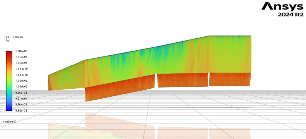
Overview
The problem required a team of students to design a fixed-wing aircraft, combined with a thrust producing device, capable of generating very high coefficients of lift. The designs were validated using CFD software (Ansys Fluent). The design parameters and constraints are given below.
Problem Statement
Design Targets
- Target \(C_L = 6.5\) Envelope: 6-8 (Bonus for 8+)
- Target \((L/D) > 5)\) with flaps
- Target \((L/D) > 20)\) without flaps
- Minimum lift target = 15 kg @ 20 m/s \(V_{\infty}\)
- Minimum freestream velocity with flaps deployed [Takeoff mode] = 20 m/s
- Minimum freestream velocity with flaps retracted [Cruise mode] = 80 m/s
- Thrust Envelope: 0.5 < T/W < 0.65 (W = 15 kg)
Constraints
- Powered lift must be generated from the thrust plant, no other power system is allowed.
- Tilt-Wing/Tilt-Rotor Designs are NOT allowed.
- VTOL Configurations are NOT allowed.
Methodology and Technical Work
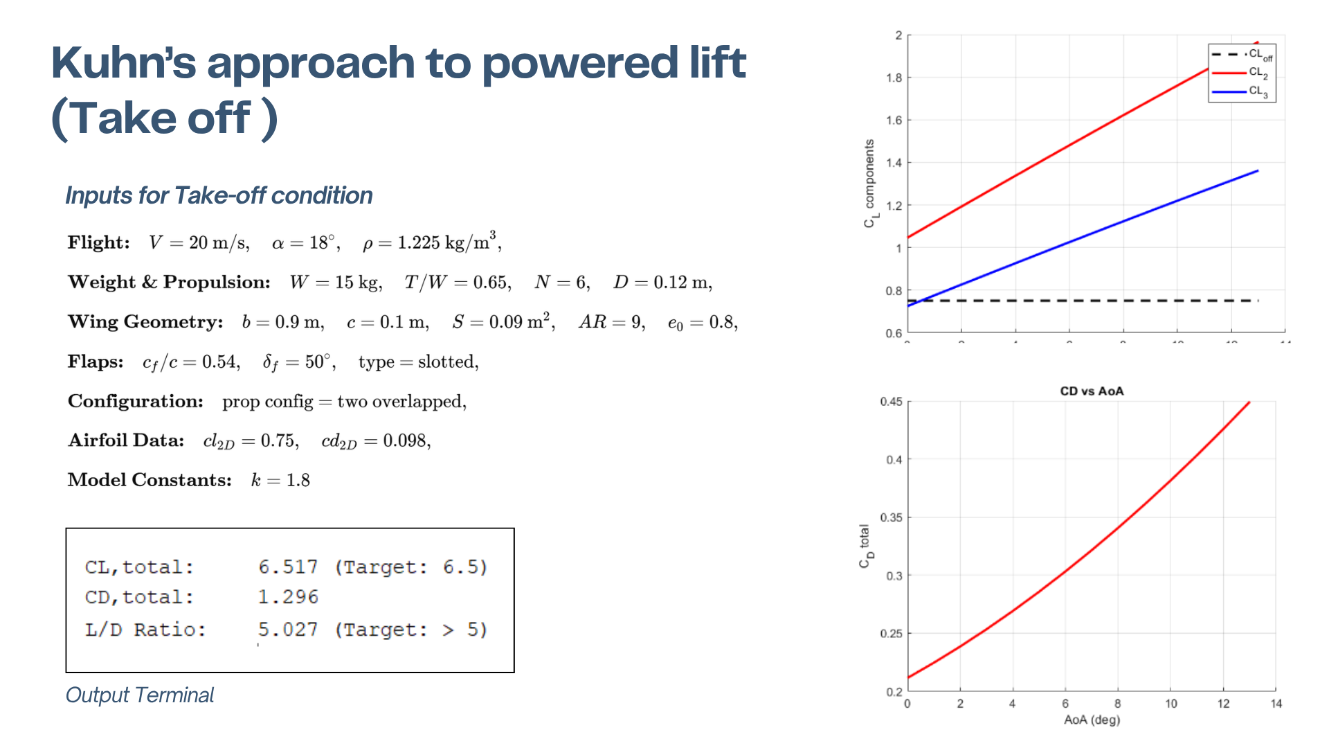
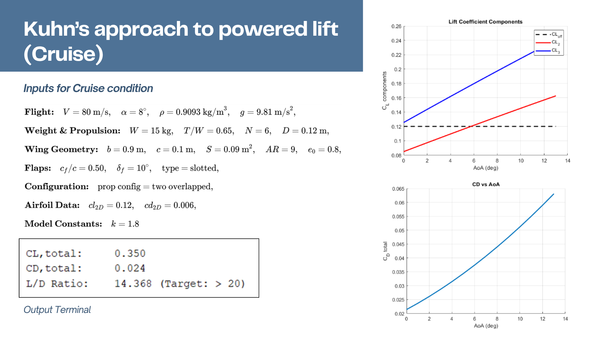
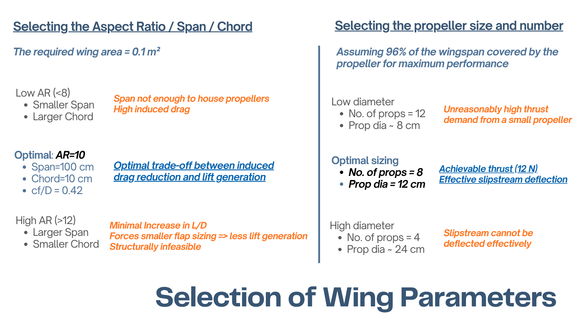
We identified that wing setups similar to typical commercial aircraft would not meet the design criteria. For acheiving them, we proceeded with high-lift setups such as externally blown-lift configurations (propellers), combined with a single flap. Initial mathematical modelling using Kuhn's approach provided us with estimates of \(C_L\), \(C_D\) and \(L/D\) during takeoff and cruise conditions. A suitable wing geometry (span, chord, aspect ratio) was chosen based on physical constraints of housing the propellers, trade-off between lift generation and induced drag .
The thrust device used was a propeller. It was important to obtain blade geometry that results in uniform axial velocity, since it results in superior lift augmentation and simplistic approach to modelling. Moreover, CFD modelling assumes near-uniform wake velocities. The blade geometry was modelled using BEMT, followed by preliminary validation of uniform wake velocities using QProp, with high-fidelity simulations using Ansys' Virtual Blade Model.
With preliminary estimates of wing geometry and propeller sizing, the main airfoil was chosen for peak \(L/D\) and trailing edge geometry (reagrding flap interaction) and a flap airfoil for peak \(C_L\). NASA SC(2)-0412 and NACA 6415 were chosen for the main wing and flap respectively.

Through iterative CFD, it was discovered that a tilt in the propeller with respect to the longitudinal axis provided better performance. The optimal angles of attack and relative positioning of the flap were identified for takeoff and cruise conditions.
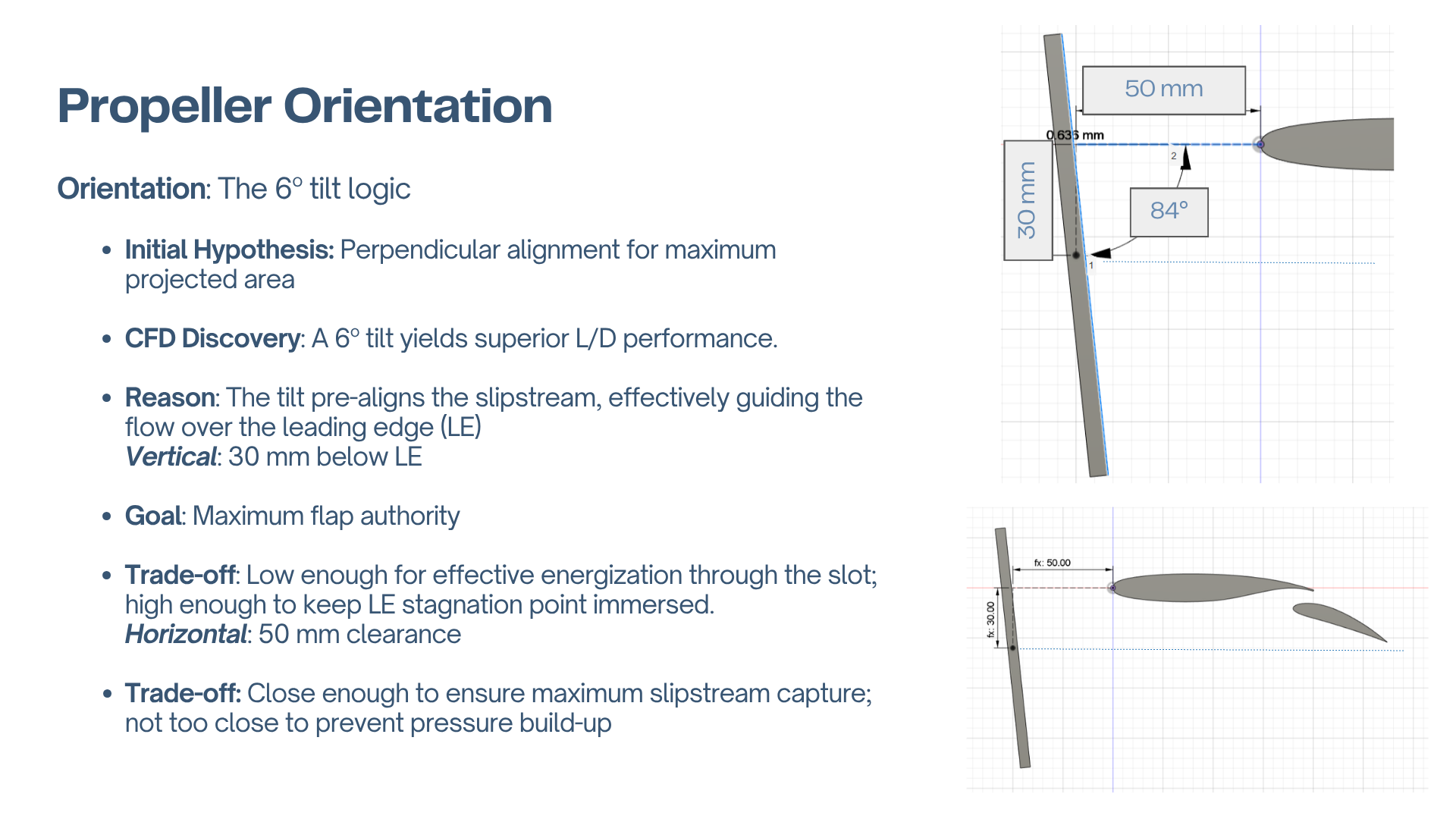
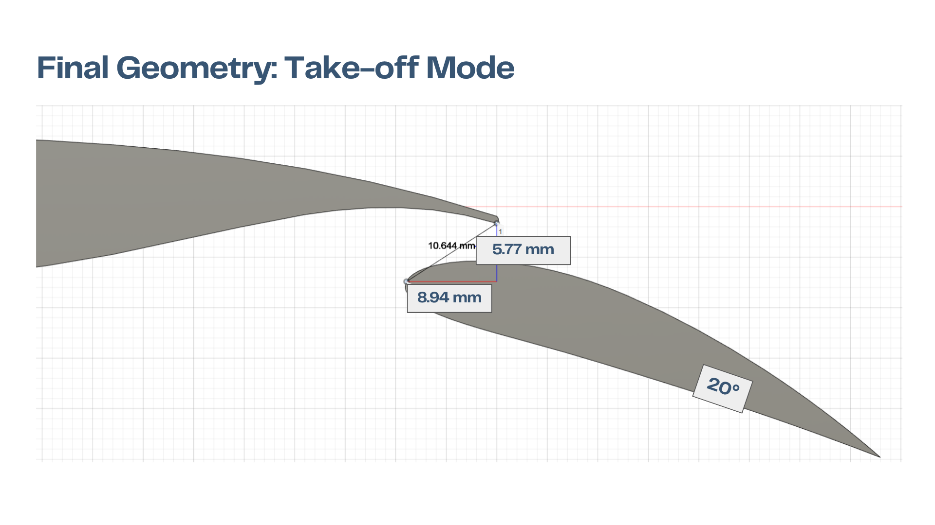
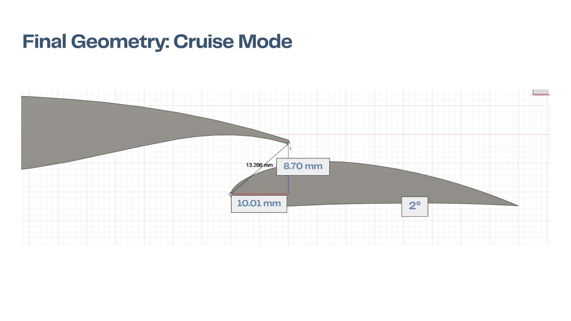
With the airfoil geometry now defined, a preliminary 3D model was developed by considering a simple extrusion of the 2D airfoil surface. The width of the extrusion was decided by matching the lift force target. (Note: The propeller is always kept at a fixed distance from the leading edge of the wing, regardless of sweep or taper. This is to ensure that the flow is generated uniformly over the wing surface across the span.) Keeping this as a baseline (Model O), we wanted to improve on this model by varying 3D wing parameters such as sweep, dihedral angle, taper, twist, etc.
Since 3D CFD is resource and time expensive, we looked towards nature for inspiration and decided to use principles of biomimicry. Using this paper on Aerodynamic Design and Optimization of a Wandering Albatross, we took their existing 3D model and modified it to match the required constraints and design targets.
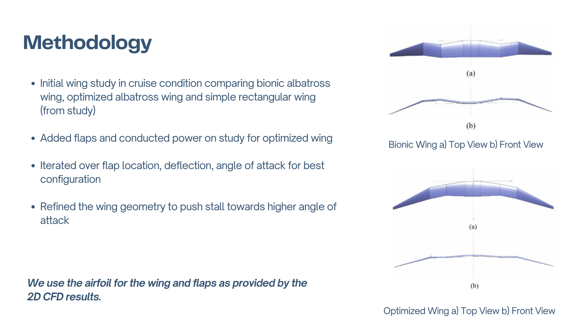
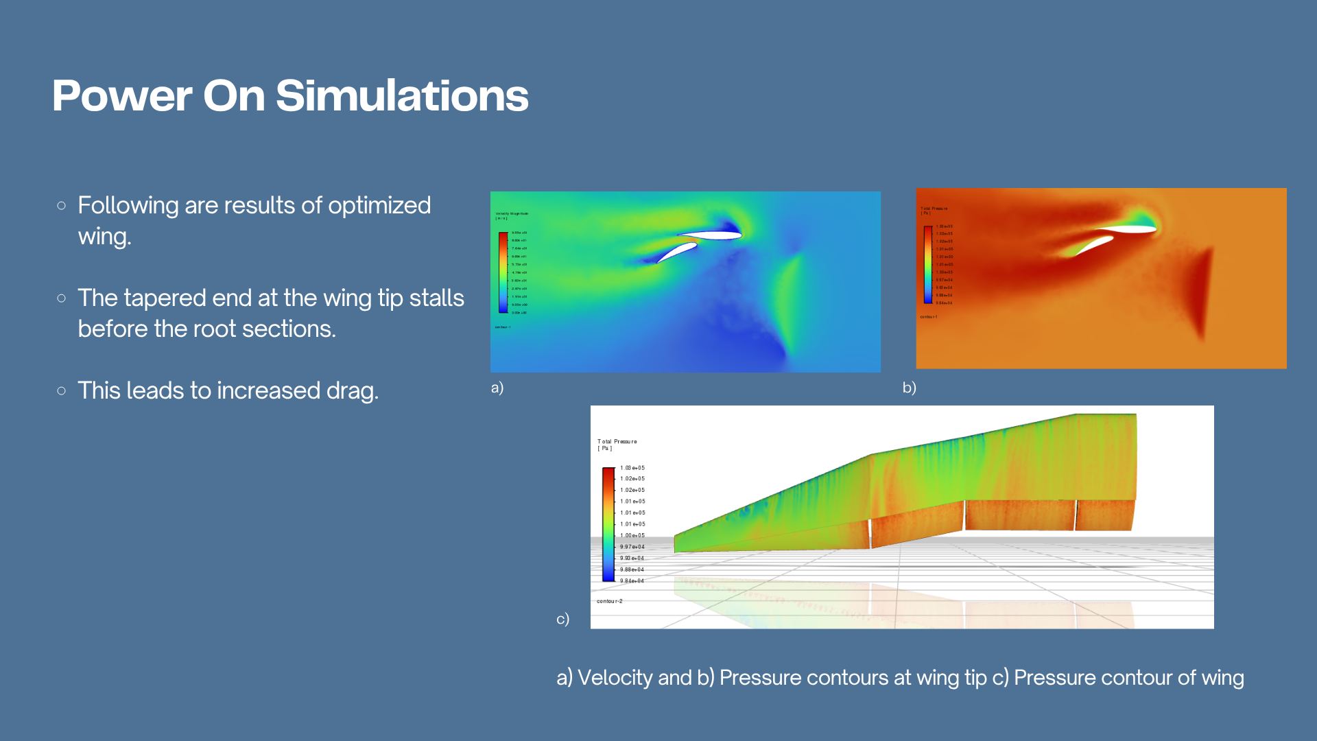
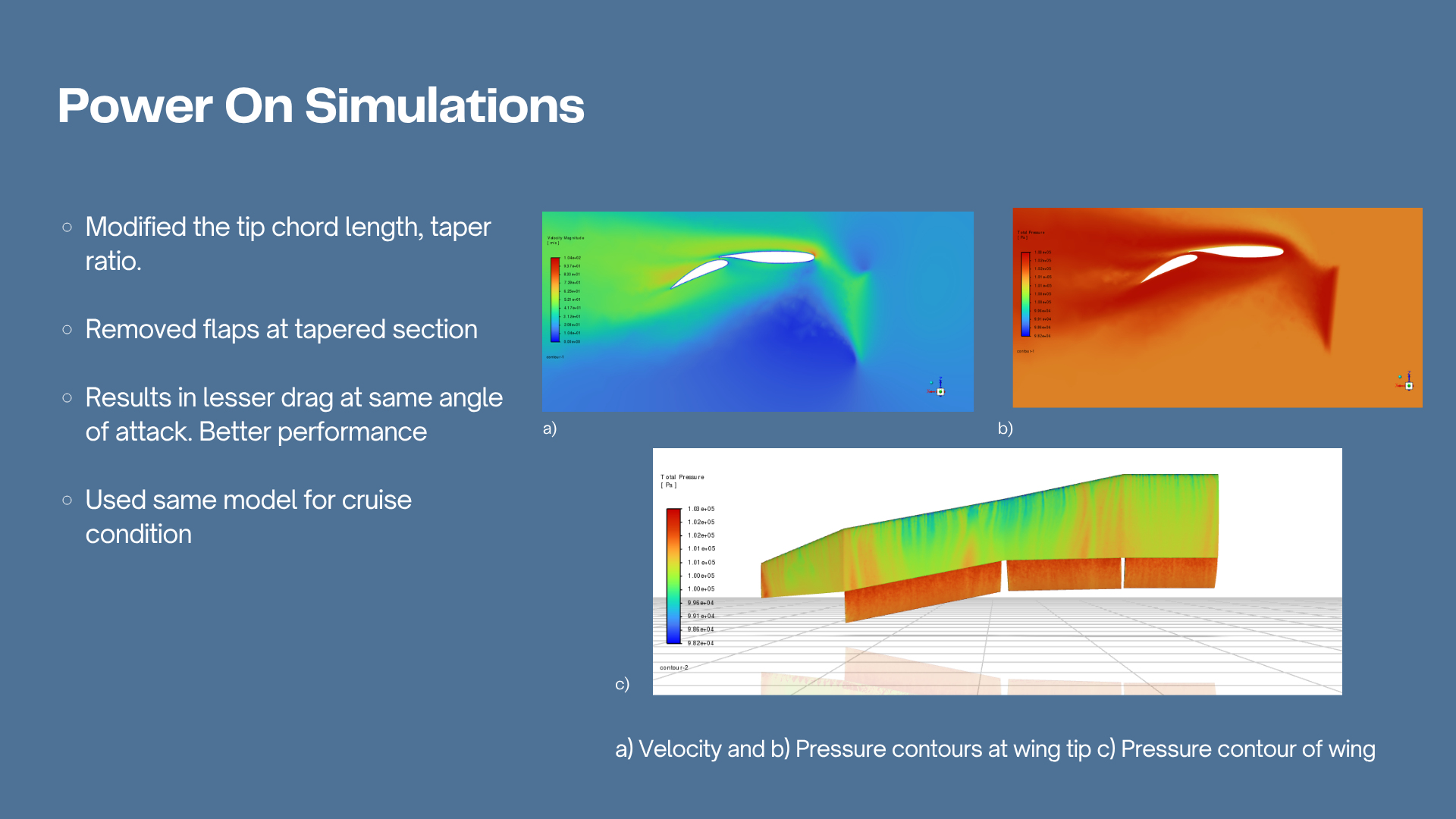
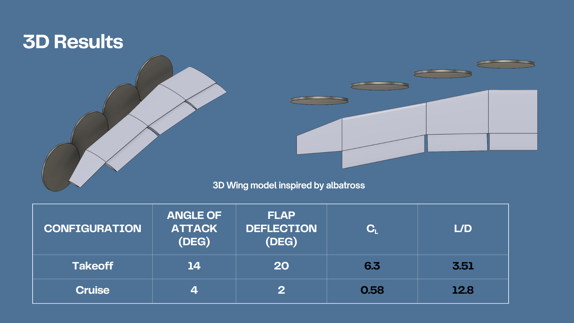
In the paper, they model a bionic albatross wing (Model A) and optimize the 3D parameters to acheive higher \(L/D\), higher peak \(C_L\) and lower minimum \(C_D\) (Model B). On importing Model B into the CFD solver, we found that the tip section begins to stall much before the rest of the wing, impacting performance drastically. This led us to increase the tip section chord length, and decrease the taper ratio. Furthermore, the flaps at the tapered region were removed, due to excessive drag generation (Model C). Overall, this resulted in a 21% higher \(C_L\) and 7.4% lower \(C_D\) compared to Model O (simple extrusion).
Results
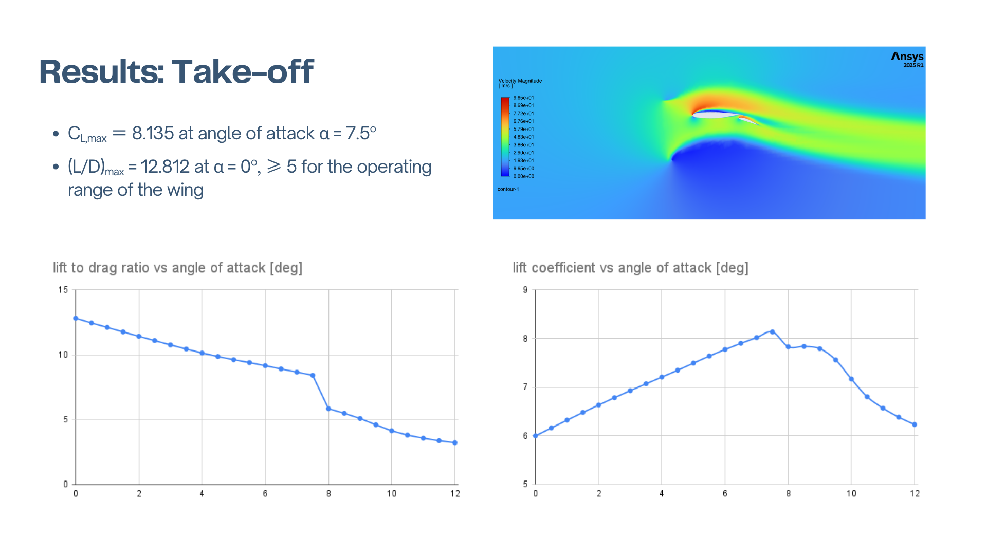
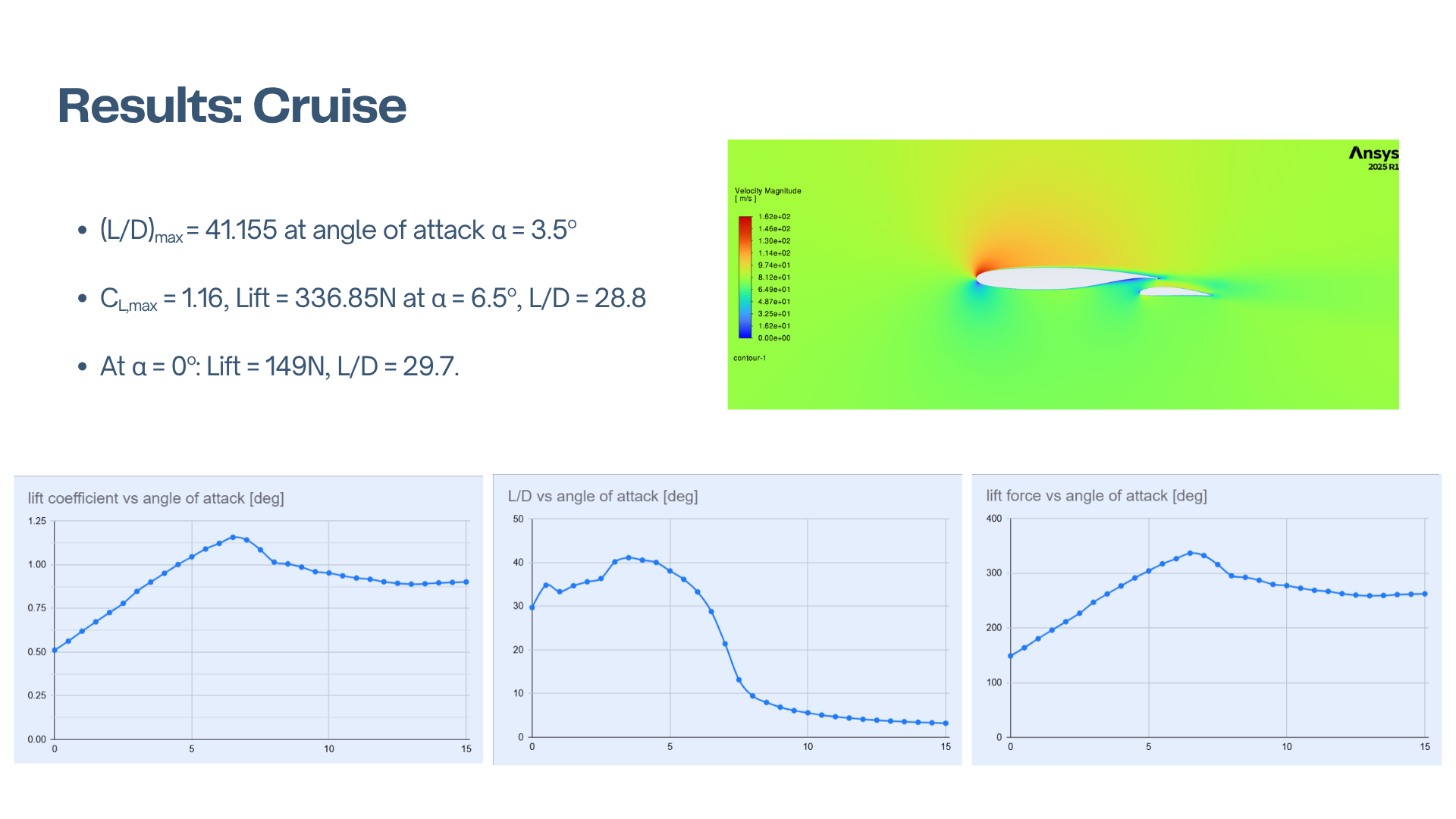
The 2D results are given in the figure below, for the configurations mentioned previously
The 3D results are given in the figure below for Model C, which was presented as our solution to the problem.
Tools
Acknowledgements
A team of students worked on this problem comprised of: Arnav Prashanth, Vishnu Anand, Kaivalya Mase, Ashish Sam, Aadi Sinha, Srikanth and Taha Mohiuddin